CHAPTER ONE: INTRODUCTION
1.1 Abstract
Computer application for power systems is one of the many technologies
undergoing rapid evolution. In this area of research, the engineer attempts
the following:
In the operation of a power system, the most often used simulation tools are Loadflow, Short
Circuit and Dynamics Programs, considered to be in their "second generation", characterized by
an interactive environment complete with graphics and full screen text editor, On-line help
facility and windowing. In MS Windows, the process is intuitive. Learning how to use a new
software is less painful. There is the use of mouse click, drag and drop. You can initiate
information or process on the graphics itself.
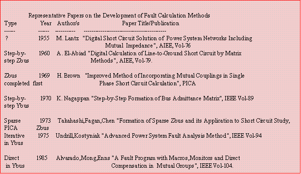
The first short circuit or fault problem was solved by a Gauss-Siedel loadflow type in 1955.
Then came the bus impedance matrix which matured by axes discarding technique to solve large
systems. As early as 1971, W.Tinney has already thought of using Ybus matrix in fault
calculation, thus utilize its outstanding property of sparsity. Although the mathematical
derivation of the sparse Zbus from the factored Ybus is very simple, it was not until 1973 that a
paper came out. Since then it became an industry algorithm.
Only one software package is known to employ the iterative method of mutual coupling
compensation. Two papers describe their so advanced short circuit programs but do not explain
their procedures for coupling compensation. This book demystifies a direct procedure for mutual
coupling inclusion in Ybus matrix. The direct method is incorporated into an interactive fault
program that will allow it to be run in a microcomputer while retaining the same features and
speed as the mainframe version.
The manual short circuit calculation of a 10-node network with more than one source of
generation requires tremendous efforts and is prone to errors using real or complex numbers.
The advent of low cost personal computers (PCs) and improved computing methods simplify such task.
This book treats the once famous full matrix Zbus with axes discarding. The latest
state-of-the-art technique of short circuit calculation using factored sparse Ybus will not be
completely understood without the knowledge of the Zbus building algorithm. It is the purpose of
this book to explain the mathematics and computing techniques, thus bridge the wide gap
between academics and industry practice. Equations are derived first before numerical example is
explained in detail.
A good contribution of this book to the scientific community is the direct method of forming
the Ybus matrix with mutual coupling compensated.
1.2 Historical Development
For several decades, short circuit calculation was computed using the elements of the bus
impedance matrix known today as Zbus. This matrix can be formed in a step-by-step procedure,
the method of Ahmed El-Abiad [1,2,9]. Zbus is square and full, although a technique is employed
to store only the upper triangle including the diagonal in linear array (vector). Only as big as 100
busses can be stored on that vector because of large core memory required and computing time.
To be able to solve network of more than 100 busses, a method of deleting an unwanted rows and
columns is employed. Known as "axes discarding", [9,15] this method can now accommodate as
large as 1500 busses, 2500 branches and 100 coupled pairs on a 640 Kb core memory. A good
example of this is the PECo Network Fault Program (Philadelphia Electric Co.) [15].
In 1973, a very significant innovation was formulated by Chen et. al. [7], where only the first
neighbourhood Zbus elements are computed from a factored bus admittance matrix, Ybus. Such
matrix is called "sparse Zbus" because it has the same sparsity as the Ybus. The method of "sparse
Zbus from a factored Ybus" could now solve very large network at a shorter computing time.
Since then, it became the standard procedure in short circuit algorithms, as Sttot/Alsac's "Fast
Decoupled" is to loadflow [24].
One most important aspect of research is the inclusion of mutual coupling in the zero
sequence network. There are two methods of including mutual coupling in the "step-by-step"
Zbus. The first one is by El-Abiad [1]. Each branch is added to the Zbus one at a time. The
coupling effect is immediately added to the partial Zbus. The second method by Brown/Storry [3]
compensates the coupling effect only after the Zbus is completed. The full Zbus matrix is first
constructed by step-by-step algorithm using line parameters modified to remove all coupling
effects, then the matrix is corrected to consider coupling.
One can also construct the full Zbus matrix using the factored Ybus method of Chen, then
correct it to include coupling. This procedure will not be practical for more than 100 busses
because of huge memory storage required.
In order to preserve sparsity in the sparse Zbus generated from factored Ybus using Chen's
algorithm, coupling must right away be included in the Ybus matrix. Nagappan [4] showed that
mutual coupling can be included in the Ybus matrix in step-by-step procedure. Undrill [8]
includes coupling iteratively on the Ybus matrix. Enns discussed that his program uses a direct
method of including the effect of coupling in Ybus. In Nagappan's paper [4], Ramarao commented
that a direct method is used in Cleveland Electric's program. The next batch of papers [10,11] on
short circuit calculation did not expound on how they include mutual coupling in the Ybus matrix.
Shown below are representative papers in chronology depicting the development of modelling
in fault calculation. A chapter in the Reference contains much more than what is given below.
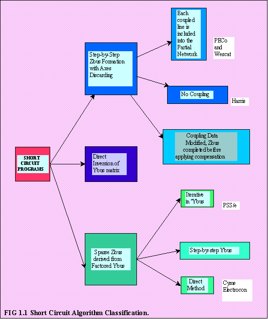
Shown below is a diagram showing the methods of short circuit calculation and its
corresponding brand name. The brand name is only a representative example.
1.3 About this Book
This book will discuss several areas of research, all necessary to implement an interactive fault program.
Introduced first is the modification on the method of K. Nagappan such that the maximum size
of the primitive matrix is only the number of branches in the coupled group. Each group is
processed independently and only the branches affected by the coupling effect are modified. For
each group, a step-by-step formation is also done, thus matrix size and computer time is reduced.
Programming technique is also applied so that there is no more testing whether the added line is
a BRANCH or a LINK.
The method of K. Nagappan influenced the author in deriving an equation for the "direct
method". This method uses the singular transformation, i.e., Ybus= A(transposed)*[y]*A where A
is the bus incidence matrix. The maximum size of [y] is only the number of branches involved in a
coupled group, similar to the modified "step-by-step" Ybus formation of Nagappan.
This direct method is shown to be optimal in terms of code and inclusion of parallel coupled
branches. Once mutual coupling is included in Ybus, the Zbus can be generated. Fault information
is now ready.
Also included here are topics on areas of:
Fault Output Options - like bus fault summary, branch contributions for NBACK>1,
monitored
branch, sliding fault, line-end fault, single outage, and submatrix printing.
Test for Network Connectedness - and also for undefined and floating busses and islands.
Programming in C/C++ and Windows 3.1 and Windows 95
1.4 Description of Fault Program and Options
The computer program, user guide and data described here can be
downloaded. Computer speed for a data consisting of 307 busses, 460 branches, 73 coupled pairs resulting
to 16 fills due to coupling, 90 due to LU factorization is almost instantaneous with today's PC. Described in more details about program options can be found on the User's Guide.
A. Fault Summary.
Gives bus number/name, its corresponding voltage level and its 3-Phase fault, 1-Phase to
ground, Line-to-line fault levels in Mva and Amperes.
B. Branch Contributions.
The first screen page displays all bus information, followed by branch contributions due to
3-Phase fault and 1-Phase to ground. Default depth of neighbourhood is 2.
C. Monitored Branch.
This option is used if a branch contribution is only the information needed and perhaps the branch
is located several neighbours away from the faulted bus.
D. Sliding or Mid-line Fault.
This is a fault located along a line where a user has to insert a dummy bus in the absence of this
option.
E. Line-end Fault.
This is a fault located on the end of a line and at the same time disconnecting the faulted end at a
bus. In the absence of this option, the user has to edit the data file.
F. Single Outage.
Performing fault calculation on a bus where one of its branch is on outage.
1.5 Comparison of Zbus formed using (a) and (b)
The method of (b) has the following attributes compared to (a);
1.1 Abstract
1.2 Historical Development
1.3 About this Book
1.4 Description of Fault Program and Options
1.5 Comparison of Zbus formed using the
"Step-by-step" and Sparse Zbus from Factored Ybus
operating system environment) thus reduce turn-around time, cost and increase flexibility.


(a). Step-by-Step Zbus Formation and
(b). Sparse Zbus from Factored Sparse Ybus.
1). The total number or locations of faults that can be solved in any one execution of
the method are not restricted. In step-by-step, this is termed as "retained busses".
2). The amount of output that can be computed for any fault is not restricted.
This is termed as
NBACK, and NOUT.
NBACK is the node count from the faulted bus.
NOUT is the number of branches on outage.
3). Power system components are
modelled accurately. Loadflow accuracy,
i.e., it can consider line charging, transformer off-nominal taps,
shunts, loads, and pre- fault voltage very easily.
4). All fault information are in core
memory, so there is no need for file swapping
when used in relay coordination program.
5). Hundredfold faster in computer execution time. Shorter and simpler computer code.
6). Integrated data base(pointer structures) with Loadflow program.
HOME
CHAPTER ONE: INTRODUCTION
CHAPTER TWO: PROGRAMMING TOPICS
CHAPTER THREE: MATRIX INVERSION ROUTINE
CHAPTER FOUR: STEP-BY-STEP ALGORITHMS
CHAPTER FIVE: DIRECT METHODS IN Ybus FORMATION
CHAPTER SIX: SPARSITY
CHAPTER SEVEN: MATRIX FACTORIZATION AND OPTIMAL ORDERING
CHAPTER EIGHT: SPARSE Zbus FROM FACTORED SPARSE Ybus
CHAPTER NINE: FAULT CALCULATIONS
REFERENCES
Copyright ©1997 by Sparsity Technology, all rights reserved.
Webmaster: JoePlanet
Source: http://joeplanet.freevar.com
This page hosted by

Get your own Free Home Page
