9.1 Zbus Matrix Modification
9.2 Manual Fault Calculations
9.3 Unified Solution for 1LG,2LG,3P,LL
9.4 Flows in Lines with Mutual Coupling
9.5 Computer Implementation of Branch flows
9.6 Computer Program, Full Matrix (FOLT.CPP)
9.7 Computer Program, Sparse Matrix (FAULT.CPP)
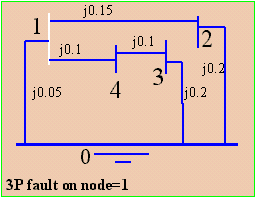
Three-Phase Fault Calculation, Manual Method
|
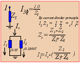
Manual method requires us to reduce the network into a
single impedance as seen by an ohm meter on node 1.
Get the series impedance on lines 1-2 and 2-0.
Z(L1)=z(12) + z(20) = j0.15 + j0.2= j0.35.
I(3 phase) = 1/j0.03944 = -j25.3572 pu.
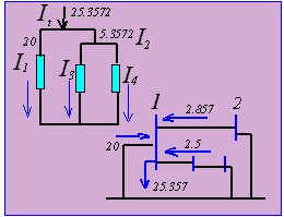
Also I(3)=-j5.3572*(0.35/0.75) =-j2.5
|  
|
|
Check By Using the elements of Zbus
k=1, P=2, Q=1 
I(2,1)=[(0.03944 - 0.02254)/0.15]*(-j25.3572) = -j2.857 pu |
|
A line may be opened by adding a line in parallel with the existing one with a negative impedance of the original. A line conversion can also be implemented by adding a line such that the equivalent impedance of the original one and the added line has the value of the desired conversion. Use Types-2,-4 or -6. During a fault study it is desirable to modify the Zbus for sliding fault, line-end fault and line outage. The best method is to extract a small matrix whose elements are the one needed in branch contributions for a desired NBACK.
|
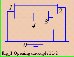
Opening a non-coupled line
Opening line 1-2 will result to z(1,2)=infinity. What should
be added to line 1-2 to make z(1,2) = infinity? Answer: negative z(1,2).
| 
|
with line 1-2 added and x= -0.15. The resulting Zbus is
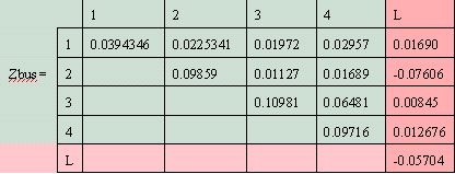
Z(L,i=1)=Z(P=1,i=1)-Z(Q=2,i=1)=0.0394346-0.0225341=0.0169
...up to
Z(L,4)
Z(L,L)=Z(P=1,P=1)+Z(Q=2,Q=2)-2Z(P=1,Q=2)+z(P=1,Q=2)
=0.03943+0.09859-2(0.022534)+(-0.15)= -0.05704
After Kron Reduction,
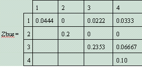
This Zbus will be the same if it is formed from an input data without z(1,2).
Opening a coupled line
Flows in the Zero Sequence Network with Mutual Coupling
The line flow in the positive sequence is
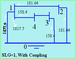
Example Fault Calculation SLG with Coupling
Output from sparz.exe
Opening line 1-4 will require a coupling matrix as shown below. Line 1'- 4' is not coupled to line 1-4. Its self impedance is the negative of line 1-4.

Here P=1', Q=4'. There are 3RS (RS= 1-4, 1-2, 4-3). The use of prime is for convenience only. It is not shown in a program code. Applying Type-6,
Z(L,i=1)=Z(P=1,i=1)-Z(Q=4,i=1)+ [y(PQ,RS)...][Z(R,i) - Z(S,i)...]/y(PQ,PQ)
Z(L,1)=Z(1,1)-Z(4,1)+[y(1'-4',1-4)*[Z(1,1)-Z(4,1)]+y(1'-4',1-2)*[Z(1,1)-Z(2,1)]+
+y(1'-4',4-3)*[Z(4,1)-Z(3,1)]]/y(1'-4',1'-4')

Z(L,1)=0.08617-0.06596+[(-0.9375)*[0.08617-0.0596] + 1.875*[0.0861-0.03723]
+(-1.25)*[0.06596-0.03191]]/(-4.0625) = 0.01276
...Z(L,4)
Z(L,L)=Z(P,L)-Z(Q,L) +(1+[y(PQ,RS)...][Z(R,L)-Z(S,L)...])/y(PQ,PQ) = -0.04255
and after applying Kron Reduction results to,
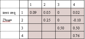
which will be the same result if we rebuild the matrix
from start without line 1-4.

This is also the equation for the zero sequence, if line P-Q is uncoupled.Q

From the coupling equation as shown on the figure,
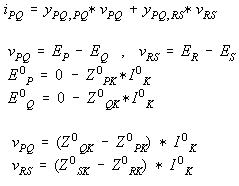
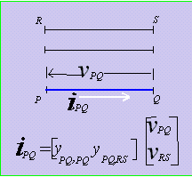

Where R-S can be more than one item. Note that 
From Fig_1, Table_1 of section 4.2, the positive/zero Zbus, x-only is,
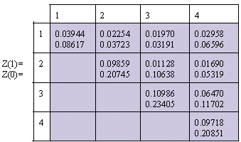
For a single-line-to-ground fault on bus=1,
 = -j605.877 Mva.

 = 1 - (-j6.05877)(j0.03944)= 0.76104 pu,
 = 0 - (-j6.05877)(j0.08617)= -0.52208 pu,
 ,
,
 = 0 - (-j6.05877)(j0.03944)= -0.2389 pu
These voltages are in real numbers because (-j)*(j)= +1.


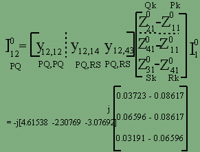
 =solved using coupling formula.

The desired flow is from P=2, to Q=1, but what is available
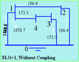
in [z] as shown on the coupling matrix above is P=1, Q=2. Solve instead  then just reverse direction. See the figure at the right side for easy interpretation.
 = (-0.22587 +0.046638 +0.104769)*(-j605.87) = j45.119 Mva
From the right side figure, the result of (0.03723- 0.08617)*4.61538) is -0.22587 as shown above. Also (-j)*(j)= +1. The (-j) from the Figure is for the admittance, the (+j) is for the impedance.



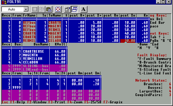

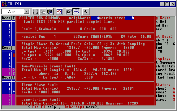
Output Node information from JPFault2.exe for a fault at node=1
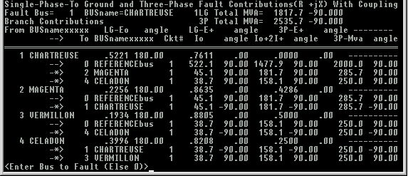
Branch Contributions from JPFault1.exe for a fault in node=1.
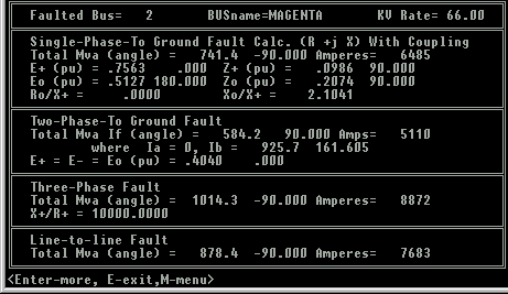
Output Node information from JPFault1.exe for a fault at node=2
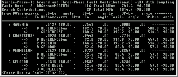
Branch Contributions for a fault in node=2. You can compare these last screen dumps to the scrollable output. Source code from this scrollable output is shown at
Chapter 8. Sparz
HOME
CHAPTER ONE: INTRODUCTION
CHAPTER TWO: PROGRAMMING TOPICS
CHAPTER THREE: MATRIX INVERSION ROUTINE
CHAPTER FOUR: STEP-BY-STEP ALGORITHMS
CHAPTER FIVE: DIRECT METHODS IN Ybus FORMATION
CHAPTER SIX: SPARSITY
CHAPTER SEVEN: MATRIX FACTORIZATION AND OPTIMAL ORDERING
CHAPTER EIGHT: SPARSE Zbus FROM FACTORED SPARSE Ybus
CHAPTER NINE: FAULT CALCULATIONS
REFERENCES
 =(j0.35*j0.4)/(j0.35+j0.4)=j0.18667.
 =(j0.05*j0.18667)/(j0.05+j0.18667)


